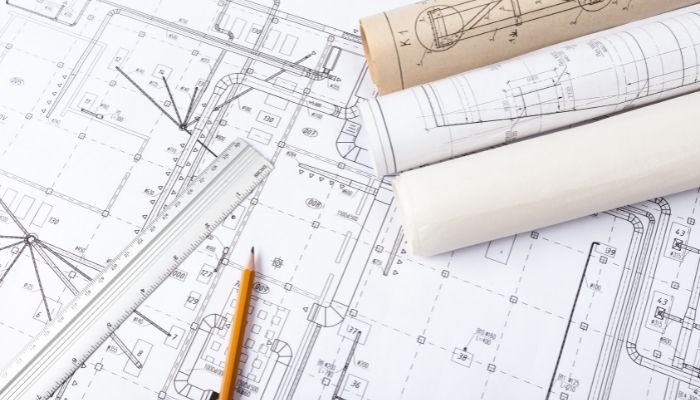
When a Revit Fabrication is being developed, and it is time to represent it in plans or specific views, the graphics configurations are essential. Sometimes they even become crucial to be able to represent an element. Since no matter how much we have modeled. If we don’t do a couple of basic settings later in the views, this effort will be overshadowed by poor rendering that doesn’t do our project justice. Especially if, in the end, the recipient will only see the plans.
There is probably a not-so-famous one within the Revit configurations, fill patterns involved in many categories; materials, visibility and graphics settings, fill regions, and detail elements.
The new economy is the current perspective of understanding the relationship between technological innovation and economic productivity in the different productive sectors. The new economy is characterized by digital methodologies, the values of collaborative work, and the rethinking of the traditional modus operandi.
The concept is also manifested in the construction, and like this, it adapts to the new times.
With this premise of innovation and technology, more and more companies in the construction sector are working with the BIM (Building Information Modeling) methodology. It is a new system applied in engineering, based on the values of the new economy and collaborative work. With good use of the methodology and good management of the implementation software, we ensure that all professionals and disciplines (belonging to different sectors) can work on a single project.
Revit Fabrication MEP is, to this day, the program that best summarizes the values of this work system and the one that best allows optimization of the BIM methodology. The characteristics that define Revit MEP are, at the same time, the advantages that you are missing as a professional if you do not already use it. We discuss them below.
Revit Fabrication Workflow: Design, Construction, And Management
Revit and its interaction with other software allow the development of the same project throughout the life cycle. The tool allows from an early pre-design of facilities to the level of a construction project divided into phases, in cooperation with the Navisworks tool for its visualization and coordination. Also, it allows possible manufacturing plans with Fabrication until the model is focused on Facility Management with the EcoDomus tool.
DESIGN OPTIMIZATION AND FACILITY ANALYSIS
Revit Fabrication MEP allows the design of installations in a three-dimensional format, avoiding a 2D design methodology, thus having greater control over the coordination of all the model elements.
On the other hand, one of the most potent functions offered by the software consists of classifying elements by systems. Before talking about the advantages of this function, a system is a set of MEP elements connected and classified to define the function for which they have been designed.
A good example that can help understand the concept would be: in the case of a network of air ducts; the systems could be classified by the supply of supply air, stale air, or return air, among others, while a distribution network of pipes could be classified, for example, as domestic hot water, sanitation, and fire protection.
These types of classification are defined according to the project’s requirements and, therefore, can be unlimited.
Now yes, the advantages of this function are: to allow calculations of pressure losses and static pressure and control the flow of each of the connected elements of the system. Having this control of parameters, the tool allows the possibility of adjusting the dimensions of the facilities to end up obtaining a more optimal design.
On the other hand, another of the possibilities offered by the realization of systems is the generation of automatic designs of ducts and pipes between elements of the same system, which can help in a pre-design phase of installations and in facilitating the modeling process. from the same.
Finally, all this project information can be extracted quickly and concretely from all the modeled elements, allowing the user to redesign installation systems, extract planning tables, and extract measurements from the elements as something very productive.
OBTAINING DOCUMENTATION
Once the project is finished, the software offers to obtain 2D plans and export them to CAD. This generation of documentation can be viewed in the desired way, allowing to continue with each company’s standards, but without forgetting the added value of being a 2D documentation coordinated with the other disciplines due to the follow-up of the BIM methodology.


